Series Circuits Provide a Continuous Loop Through Which Current Can Flow
What is the difference between a series circuit and a parallel circuit? Although circuits with only one battery and one load resistance are simple to evaluate, they are rarely used in practical applications. Typically, we come across circuits that have more than two components coupled together. A series circuit is one in which the entire current travels through all of the components.
What is Series Circuit?
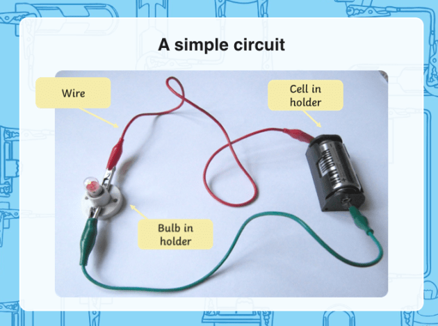
A series circuit is a simple circuit that allows electrons to pass between one or more resistors. Anything that draws power from a cell is referred to as a resistor (battery). In a series circuit, the resistor is usually a bulb. To light up the bulb, the circuit is joined to the cell from one end to the other, with no branches. All circuit components should be simply connected from one end to the cell and the other end to the bulb; any gaps or disconnections will cause the circuit to fail.
Artificial and natural circuits are the two types of circuits we have. Because the simple circuit shown below is powered by a cell, it is an artificial circuit. A fuse or circuit breaker will be installed within the circuit to prevent the flow from becoming a hazard.

Definition of a Simple Electrical Series Circuit
Understanding circuits, how they function, and how to calculate things like total resistance around various types of circuits are all part of learning the fundamentals of electronics. Real-world circuits can be complex, but you can understand them using the fundamental understanding you've gained from studying simpler, idealized circuits.
Series and parallel circuits are the two primary types of circuits. All of the components (such as resistors) are placed in a line in a series circuit, which is made up of a single loop of wire. A parallel circuit is divided into several branches, each with one or more components. Series circuits are simple to calculate, but it's essential to understand the differences and how to work with them. Visit here to know the series circuit more appropriately.
The Basics of Electrical Circuits
Only in circuits does electricity flow. To put it another way, for something to work, it requires a complete loop. When you use a switch to break the loop, the power stops flowing, and your light (for example) turns off. A simple circuit is a closed loop of a conductor around which electrons can travel, typically consisting of a power source (such as a battery), an electrical component or device (such as a resistor or a light bulb), and conducting wire.
To understand how circuits function, you'll need to learn some basic terms, but most of the phrases will be known to you from everyday life.
The difference in electrical potential energy between two points per unit charge is referred to as a "voltage difference." When two terminals of a battery are connected in a circuit, a potential difference between them is created, allowing current to flow from one to the other. Technically, the voltage is the potential at one point, but in practice, it is the changes in voltage that matter. The potential difference between the two terminals of a 5-volt battery is 5 volts, and 1 volt equals 1 joule per coulomb.
A circuit is formed when a conductor (such as a wire) is connected to both terminals of a battery and an electric current flows around it. The current is measured in amps, which equals coulombs per second.
Any conductor will have electrical "resistance," which refers to the material's resistance to current flow. The resistance of a conductor is measured in ohms (Ω), and a conductor with 1 ohm of resistance connected across a voltage of 1 volt will enable 1 amp of current to pass. The equation between these elements is expressed by Ohm's law (V=RI).
Series Configuration Circuit
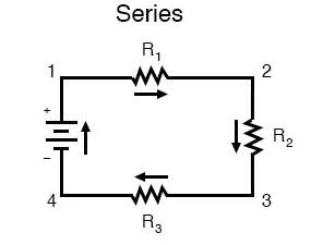
First, an example of a series circuit is presented below:

Three resistors (designated R1, R2, and R3) are connected in a lengthy chain from one battery terminal to the other in this diagram. (It's worth noting that the subscript labeling—those small digits to the lower-right of the letter "R"—has nothing to do with the ohm values of the resistors.) They only serve to distinguish one resistor from another.)
A series circuit is distinguished by the fact that current can only flow in one direction. The current in this circuit flows clockwise from point 1 to point 2 to point 3 to point 4 and back to point 1.
Voltage Drop in Series Circuit
To determine voltage drops between individual resistors in a series, perform these steps:
- Add the individual R values to calculate the overall resistance.
- Calculate the circuit's current, which is the same across all resistors because the circuit has only one wire.
- Using Ohm's law, calculate the voltage drop across each resistor.
Calculating Resistance for a Series Circuit
The distinction between series and parallel circuits is highlighted by calculating the total resistance from several resistors. The total resistance (Rtotal) in a series circuit is simply the sum of the individual resistances, so:
{R}_{total}={R}_{1} + {R}_{2} + {R}_{3} + ...
Because it's a series circuit, the path's overall resistance is equal to the sum of the individual resistances.
Other Calculations in a Series Circuit
A series circuit is significantly easier to calculate resistance than a parallel circuit, however, this isn't always the case. In series and parallel circuits, the equations for capacitance (C) work in the opposite direction. Because you have an equation for the reciprocal of capacitance in a series circuit, you can compute the total capacitance (Ctotal)
Equivalent Capacitance of Series Capacitors
All of the components in a series circuit are connected on the same path around the loop, and series capacitors are joined one after the other on the same path around the circuit. The capacitance from a single equivalent capacitor can be used to express the total capacitance of a series of capacitors.
The formula for this can be found by rearranging the basic expression for capacitance from the preceding section:
V= \frac{Q}{C}
Because Kirchhoff's voltage rule specifies that the sum of voltage drops around a complete circuit loop must equal the voltage from the power supply, the voltages must add up as follows for n capacitors:
{V}_{total}={V}_{1} + {V}_{2} + {V}_{3} + ... {V}_{n}
Where Vtot represents the total voltage from the power supply, and V1, V2, V3, and so on denote the voltage drops across the first, second, third, and so on capacitors. This, when combined with the previous equation, provides:
\frac{{Q}_{tot}}{{C}_{tot}}=\frac{{Q}_{1}}{{C}_{1}}+\frac{{Q}_{2}}{{C}_{2}}+\frac{{Q}_{3}}{{C}_{3}}+...\frac{{Q}_{n}}{{C}_{n}}
The meaning of the subscripts is the same as the previous. However, because the charge on each of the capacitor plates (i.e., the Q values) comes from the plate next to it (i.e., the positive charge on one side of plate 1 must equal the negative charge on the next nearest side of plate 2, and so on), you can write:
{Q}_{tot}={Q}_{1}={Q}_{2}={Q}_{3}={Q}_{n}
As a result, the charges cancel out, leaving the following equation. Because the combined capacitance is the same as the equivalent capacitance of a single capacitor, this may be represented as:
\frac{1}{{C}_{eq}}=\frac{1}{{C}_{1}}+\frac{1}{{C}_{2}}+\frac{1}{{C}_{3}}+...\frac{1}{{C}_{n}}
for any number of capacitors.
How to Calculate Amperage in a Series Circuit
Resistors are connected in series circuits so that the current, measured in amplitude or amperage, follows one path in the circuit and remains constant throughout. The current flows in the opposite direction of electrons through each resistor, impeding the flow of electrons from the positive end of the battery to the negative end in a single path. In contrast to a parallel circuit, there are no external branches or channels through which the current can pass.
The amplitude of the series circuit, expressed in amps or amperes, can be calculated by adding the resistance at each resistor in the circuit as R and the voltage drops as V, then solving for I in the equation I = V/R, where V is the battery voltage in volts, I is current, and R is the total resistance of the resistors in ohms (Ω). In a series circuit, the voltage drop should be equal to the voltage of the battery.
At each resistor in the circuit, the equation V = RI, generally known as Ohm's Law, holds true. A series circuit's current flow is constant, which implies it's the same at each resistor. Using Ohms' Law, you can determine the voltage drop across each resistor. The voltage of the batteries is increased when they are connected in series, so they last less time than when they are connected in parallel.
Series Circuit Examples
In everyday life, series circuits are common. Some forms of Christmas or holiday lights are examples. A light switch is another common example. In addition, the principle of a series circuit is used in computers, televisions,submersible sump pumps and other domestic electrical devices.
The Use of a Series Circuit Connection
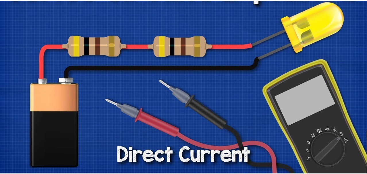
Connections between series circuits can be created in a variety of ways and using a variety of electronic components. The majority of electronic circuit designers begin by learning how to connect resistors, batteries, and LEDs in series. You'll be able to customize electronic designs to perform certain functions once you've acquired these fundamentals, which you'll usually study in your first year of college-level electronic studies.
Voltage Dividers
Resistors are used in series to divide voltages so that electrical devices with different voltage levels can be powered. Taps, which are distinct voltage levels inside the series resistor network, are then wired to other electrical components like voltage regulators, creating a constant voltage equal to the tap voltage.
Battery Voltage
When batteries are connected in series, the voltage of the batteries rises. When two five-volt batteries are connected in series, a battery with a voltage of ten volts is created. When linking batteries in series, the voltage does not have to be the same, but the ampere-hour capacity must be the same. The ampere-hour capacity of a battery is a measurement of how long it can supply a certain amount of electrical current. A 20 ampere-hour battery, for example, can provide 20 amperes for one hour or five amperes for four hours.

Series vs. Parallel Circuits
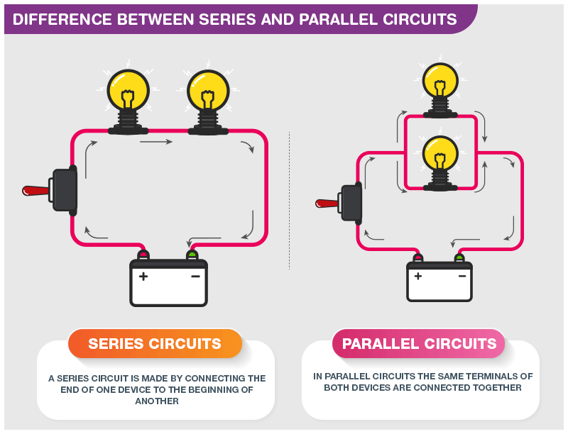
The arrangement of components in the two basic types of circuits defines them.
"A circuit with the components arranged in a straight line, such that all of the current goes through each component in turn," says a simple series circuit definition. The two resistors would be in series if you created a basic loop circuit with a battery connected to two resistors and a link running back to the battery. As a result, the current would flow from the positive terminal of the battery to the first resistor, then to the second resistor, and finally back to the battery.

A parallel circuit is not the same as a series circuit. A circuit with two parallel resistors would divide into two tracks, each with a resistor. When current reaches a junction, the same amount of current entering the junction must also leave the junction. This is known as the conservation of charge, or Kirchhoff's current law for electronics. If the two channels have the same resistance, the current will travel in the same direction. For example, if 6 amps of current reach a junction with equal resistance on both channels, 3 amps will flow down each. The circuit is then completed by reconnecting the pathways to the battery.
How to Solve a Series and Parallel Combination Circuit
All circuits can be subdivided into series and parallel circuit combinations. A parallel circuit branch could have three components connected in series, and a circuit might be made up of three parallel, branching parts in a row.
Breaking down the circuit into portions and figuring them out one by one is all it takes to solve a problem like this. Consider the following simple example: a parallel circuit contains three branches, but one of them has a series of three resistors attached to it. The key to solving the problem is to combine the series resistance calculation with the overall circuit calculation.
Read More In Linquip
- Types of Electric Circuits: All Classification with Application
- How does a Circuit Breaker Work?
- What is Resistive Circuit
- What is Linear Circuit
- What is RL Circuit
- What is RC Circuit?
- What is RLC Circuit
- What is Capacitive Circuit?
- Types of Resistor: Classification, Application, and Finally Clarification
- What is Parallel Circuit? Definition & Example
- What is Closed Circuit? Definition & Example
- What is Short Circuit? A Clear Definition & Protection Guide
- What is Open Circuit? Diagram & Example
- Difference Between Linear and Nonlinear Circuits
- Types of Electric Circuits: All Classification with Application
- What are the Differences Between Series and Parallel Circuits?
Source: https://www.linquip.com/blog/what-is-series-circuit/

0 Response to "Series Circuits Provide a Continuous Loop Through Which Current Can Flow"
Post a Comment